 |
 |
 |
| LD25 SILVER/SILVER CHLORIDE EMBEDDABLE REFERENCE ELECTRODE
Note: you can also download a pdf file of the data sheet for the LD25. Click here.
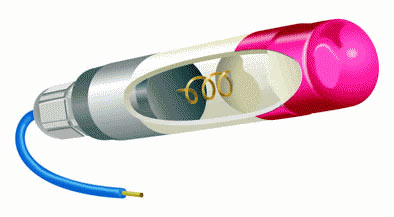
General Description The LD25 is a long life silver/silver chloride reference electrode with a stable reference potential specifically for permanent installation in reinforced concrete structures. The essential components are silver metal, silver chloride, soluble silver ions and chloride ions. Ag, AgCl(s), Cl-, Ag+ A sparingly soluble salt, silver chloride, is in equilibrium with a saturated solution of this salt which precipitates in the course of electrolysis. The reversible electrode reaction consists of silver ions going into solution and then combining with the chloride ions to form silver chloride. Thus its potential is determined by the following reactions: Ag <> Ag + e- Ag+ + Cl- <> AgCl(s) Ag + Cl- <> AgCl(s) + e- The potential is dependent on temperature and the concentration of chloride ions in accordance with the following equation: E=E0 - RT ln [Cl-] Where E0, R, F and T are the standard potential, gas constant, Faraday Constant and temperature respectively. The reaction has been proved to obey these equations in solutions with pH’s of between 0 and 13.5. The potential is however very sensitive to traces of bromide ions which make it more negative. The electrode element has been prepared by electrolytic precipitation of silver chloride onto silver metal. This has then been embedded in a mortar containing a known concentration of chloride ions and an anti-drying agent. The housing consists of a white nylon barrel, white nylon inserts, and a cable gland rated at IP68. Specification Element Type:
Potential:
Drift:
Internal Resistance:
Polarisation Characteristics (determined galvanostatically in sodium hydroxide solution)
Dimensions:
Housing:
Cable:
Expected life:
Other Features:
Installation Procedure The purpose of this statement is to ensure that the reference electrodes when delivered to site are correctly stored, checked for functionality and installed. Storage The electrodes are individually numbered and delivered to site boxed with the red protective caps in place. The purpose of the caps is to protect the sensor end of the electrode from contamination or damage whilst in storage. With the delivery inside the box there will be a calibration certificate for all the delivered electrodes. This document should be kept with the record documents for the contract. The calibration certificate is a record of the individual reference potentials measured against a saturated calomel electrode (SCE) at 20oC under laboratory conditions. The Corrosion Engineer may refer to the information on the calibration certificate during the operation of the monitoring system. Pre – installation Functional Check The purpose of this procedure is to check that the electrode potential is stable. Electrode Installation Procedure :-
The important points to remember are that the concrete should be pre-wetted , the red cap removed and the cable supported while the concrete is placed and cured. The electrode-measuring tip must be fully encapsulated by the repair mortar. Variations on this procedure can be acceptable subject to agreement by the Design engineer. In some cases the concrete is cored and the electrode placed in the core hole with the concrete then made good. At other times to ensure good contact the electrodes are pre-potted in a mortar cylinder before embedding in the concrete. Copyright © 2006 [Castle Electrodes]. All rights reserved.
|